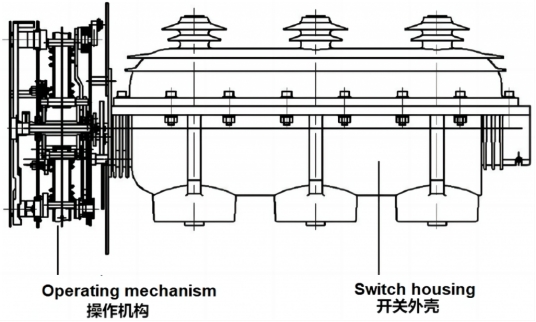
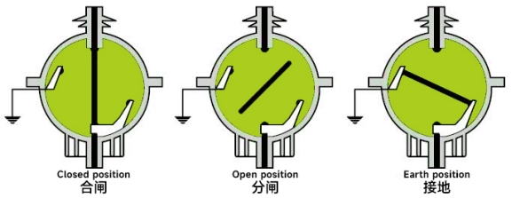
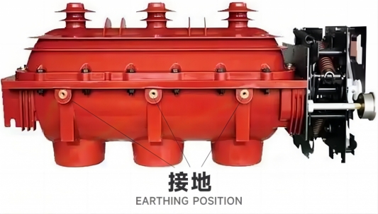
The 24kV Indoor SF6 Switch-Disconnector FL(R)N36 Load Break Switch (LBS) and fuse combination unit is designed for use in three-phase AC 50Hz ring networks or terminal applications within power stations and industrial facilities. This unit provides reliable load control and protection for 24kV power systems, efficiently handling load current, closed-loop current, no-load transformer, and cable charging currents. The combination unit can interrupt any current up to its rated short-circuit breaking current, making it ideal for use in ring main units, box-type substations, and other comprehensive electrical setups.
This product is particularly suited for power distribution in urban residential areas, small secondary substations, switchgear rooms, industrial and mining enterprises, large shopping centers, airports, subway systems, hospitals, sports facilities, and similar applications.
The FL(R)N36 series meets the requirements of GB3804, GB16926, IEC 60265-1, and IEC60420 standards, ensuring compliance with international performance and safety benchmarks.


Use Conditions
1. Ambient air temperature: upper limit +40℃, lower limit -15℃.
2. Environmental humidity: The daily average relative humidity is not greater than 95%, and the monthly average relative humidity is not greater than 90%.
3. Altitude: The maximum altitude of the equipment installation site is 2000m.
4. Earthquake: The earthquake intensity does not exceed 8 degrees.
5. There is no serious pollution in the surrounding air, such as dust, smoke, chemical corrosives, flammable gases, gasoline and salt agents, etc.
6. When the operating environment conditions are different or there are other requirements, consultation with the manufacturer is required.
Operating Mechanism
The spring operating mechanism of the load switch and its combined electrical appliances is divided into single spring operating mechanism and double spring operating mechanism. The FLN series load switch equipped with a single spring operating mechanism is mainly used for the incoming and outgoing line control unit. The FLRN series load switch-fuse combination appliance equipped with a double spring operating mechanism is mainly used for transformer protection units.
Maintenance and Care
Under normal use conditions where the environment meets the requirements of the installation and operation instructions, the switch body is guaranteed to be maintenance-free for 20 years. Due to environmental differences, necessary inspection and maintenance work on the load switch is still required.
l According to the working environment, conduct appropriate visual inspection of the insulation cover between June and December, and remove dirty and damp surfaces.
l Carry out lubrication and operation inspection of the operating mechanism 1 to 2 times a year to ensure normal operation.
l For load switches equipped with pressure gauges, the readings of the pressure gauges should be checked from time to time.
l When a fault current passes through the load switch fuse combination appliance and one phase fuse blows, all three phase fuses must be replaced. When replacing, the grounding switch must be closed first before replacement, and ensure that all three-phase fuses are installed in place.