REACH TECH PRODUCTS

Outdoor Pole-Mounted SF6 Switchgear

Pole-mounted SF6 switching equipment for overhead distribution applications. Explore terminal and insulated cable arrangements, with measurement, protection, control and remote communication available through a suitably configured feeder terminal unit (FTU).

Ask about this product Explore product details

Intelligent switching for overhead distribution

This range brings together outdoor pole-mounted SF6 equipment and control arrangements for overhead distribution networks. Terminal or insulated cable connections can be selected to suit the application. Where a compatible FTU is specified, measurement, protection, control and remote communication functions can be configured for the project.

  • Outdoor pole-mounted equipment for overhead distribution applications.
  • Configurable measurement, protection, control and communication functions.
  • Terminal or insulated cable connections, depending on the selected arrangement.

Integrated primary equipment and intelligent control

The following features describe the supplied SF6 circuit-breaker and intelligent-controller configuration. Available functions and accessories depend on the selected equipment arrangement.

Primary SF6 switching equipment

  • Compact construction. A common-tank layout combines SF6 insulation and arc interruption. Maintenance requirements depend on operating duty and the applicable manual.
  • 304 stainless-steel enclosure. The switch tank uses corrosion-resistant stainless steel for outdoor service.
  • Copper-tungsten contacts. Copper-tungsten alloy contact components and tulip-type contact fingers are specified for the selected configuration.
  • Pressure relief. A pressure-relief device is provided to limit tank pressure rise during an internal fault.
  • Optional low-pressure interlock and alarm. The device can mechanically block operation at low gas pressure and provide an auxiliary signal to the controller.
  • Connection options. Terminal and insulated cable arrangements are available. Cable insulation helps reduce the risk of external phase-to-phase faults at the terminals.
  • Bushing options. Porcelain or organic-insulation bushings can be selected to suit the installation and service environment.
  • CT/RVT protection. Protection provisions for current- and voltage-measurement circuits depend on the specified CT/RVT module.
  • Voltage-sensor protection. Protection can be provided for phase-voltage and zero-sequence voltage sensing circuits.

Secondary intelligent controller

  • Communication integration. Communication capabilities are selected to suit the project. Confirm IEC 61850 support and interoperability for the specified controller, firmware and configuration.
  • Real-time processing. A digital signal processor and field-programmable logic provide processing and memory resources for protection, communications, system management and the operator interface.
  • Configurable remote functions. Remote indication, measurement and control can be configured to match the automation requirement.
  • Modular architecture. Standardized modules and a high-speed real-time serial bus support expansion and maintenance.
  • Linux-based software platform. A layered modular structure separates application software from underlying data and resources through defined interfaces. Application loading and unloading depend on the supported controller software.
  • Application development. The controller platform supports development and extension of application functions.
  • Fault-management design. Hardware/software redundancy provisions, self-diagnostics and recovery functions depend on the specified controller configuration.
  • Communication interfaces. Interfaces support local interconnection, maintenance and remote communication, according to the selected configuration.
  • Industrial-grade components. The supplied description specifies a chip operating range of −40 to +85 °C; this is a component rating, not the complete controller's ambient operating rating.
  • Outdoor enclosure design. The enclosure addresses rain, moisture, contamination and vibration, together with ventilation and heat dissipation.
  • Lightning and EMC protection. Protection and interference-immunity provisions are selected for the application; applicable test standards and levels must match the controller's supporting documentation.

Configuration examples

Illustrative configurations. Final equipment, accessories and controller functions depend on the selected configuration.

Pole-mounted switching equipment with insulated cables and an open control cabinet
Insulated cable arrangement with control cabinet
Pole-mounted SF6 equipment showing the terminal connection arrangement
Terminal connection arrangement
Pole-mounted circuit breaker with a separate enclosure and connecting cable
Arrangement with a separate enclosure
Alternative pole-mounted equipment arrangement showing the operating side
Alternative operating-side arrangement

Contact Reach Tech for model-specific ratings, switching duties, dimensions and controller options.
Specification parameters.

Typical 12 kV / 630 A SF6 circuit-breaker configuration

These data describe the supplied typical configuration and do not assign identical ratings to every gallery image. Confirm the model-specific datasheet, controller configuration and installation drawing before selection.

On smaller screens, swipe across a table to view all columns.

Circuit breaker electrical data

ParameterTypical value
Rated voltage12 kV
Rated current630 A
Rated frequency50/60 Hz
Arc-quenching mediumSF6
Insulating mediumSF6
Rated cable-charging breaking current25 A
Rated short-circuit breaking current20 kA
Temperature-rise test current1.1 × Ir (rated current)
Power-frequency withstand voltage, 1 min — phase-to-phase42 kV
Power-frequency withstand voltage, 1 min — phase-to-earth42 kV
Power-frequency withstand voltage, 1 min — across open contacts48 kV
Lightning impulse withstand voltage, peak — phase-to-phase75 kV
Lightning impulse withstand voltage, peak — phase-to-earth75 kV
Lightning impulse withstand voltage, peak — across open contacts85 kV
Rated short-time withstand current and duration20 kA for 4 s
Rated peak withstand current50 kA peak

Impulse waveform: to be confirmed for the selected model.

Construction and connection

ParameterTypical value
Overall dimensions (L × W × H), tabulated configuration1015 × 950 × 580 mm
ConstructionCommon-tank construction
OperationElectrical operation with manual operating provision
Control connector on the switch body26-pin circular connector

The tabulated dimensions apply to the configuration described in the parameter table. Use the approved model-specific drawing for final dimensions and interfaces.

Measurement sensors

ParameterTypical value
Phase-current sensor ratio/outputSelectable; current- or voltage-output interface to be confirmed
Zero-sequence current sensor ratio/outputSelectable; output type and rating to be confirmed
Phase-current sensor accuracyProtection: 5P10; measurement: class 0.5
Zero-sequence current sensor accuracyProtection: 5P10; additional low-current error specification to be confirmed
Phase-voltage sensor ratio(10 kV/√3) : (3.25 V/√3)
Zero-sequence voltage sensor ratio(10 kV/√3) : (6.5 V/√3)
Phase-voltage sensor accuracyClass 0.5
Zero-sequence voltage sensor accuracyClass 1

Sensor ratios, output type, reference quantities, burden and controller input compatibility must be confirmed for the selected configuration. Voltage ratios are reproduced as stated in the supplied technical material.

Intelligent controller data

ParameterTypical value
DC supply voltage, as listed24 V DC
AC supply voltage, as listed220 V AC
Rated frequency50/60 Hz
Phase-current setting range for short-circuit protection20–1260 A
Zero-sequence current setting range for earth-fault protection0.1–20 A
Zero-sequence voltage setting range for earth-fault protection1–100%
Overvoltage protection setting range110–185%
Undervoltage protection setting range25–90%
Controller weight, as listed25 kg

Confirm the supply arrangement, current reference and voltage-percentage bases in the applicable controller manual. These setting ranges are not commissioning settings. Controller weight does not represent the complete switching assembly.

Additional details.

Installation and commissioning

Installation, testing and maintenance must be performed by qualified personnel in accordance with the equipment-specific manual and site safety procedures.

Before installation

  1. Check the model and specifications against the order and confirm that all accompanying documents and accessories are present.
  2. Inspect the equipment for transport damage, cracked insulation, enclosure deformation, seal damage and loose fasteners.
  3. Photograph any damage and contact the manufacturer before proceeding.

Handling and mounting

  1. Use the designated lifting points and lifting arrangement for the selected model, and keep the equipment level during lifting.
  2. Bolt the unit to a flat mounting bracket. Where the four mounting points are not coplanar, use the specified packing or washers to prevent enclosure distortion.
  3. Arrange the busbar or cable connection so that the equipment terminals are not subjected to continuous tension, compression or torque.

Commissioning checks

  1. Carry out the prescribed manual or electrical opening and closing checks under the applicable test conditions, and verify reliable operation.
  2. Confirm that the pressure-gauge pointer is in the green operating range.
  3. Perform the specified overcurrent protection test and verify operation against the approved settings.
  4. Inspect and clean the equipment after installation before placing it into service.

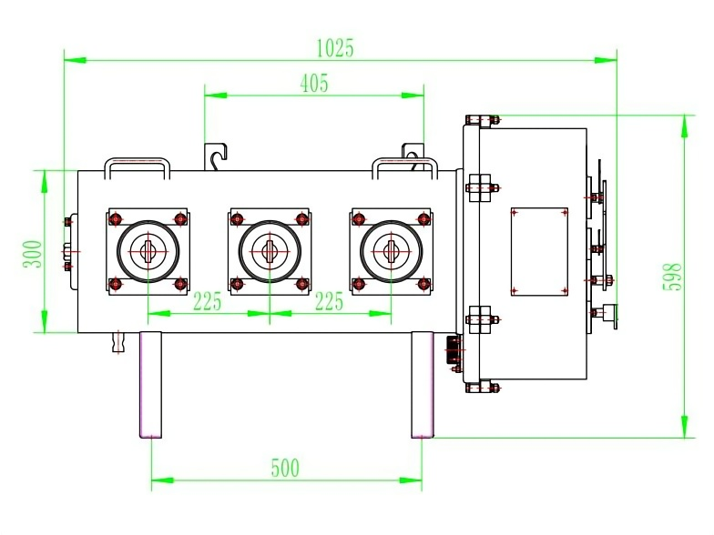
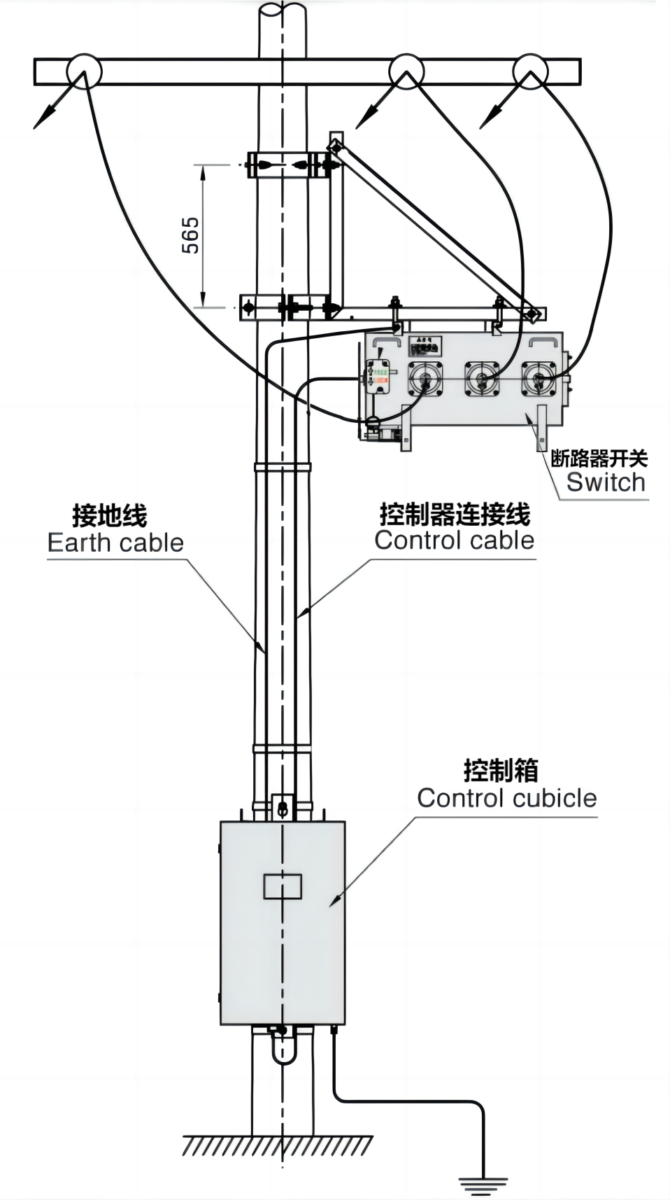
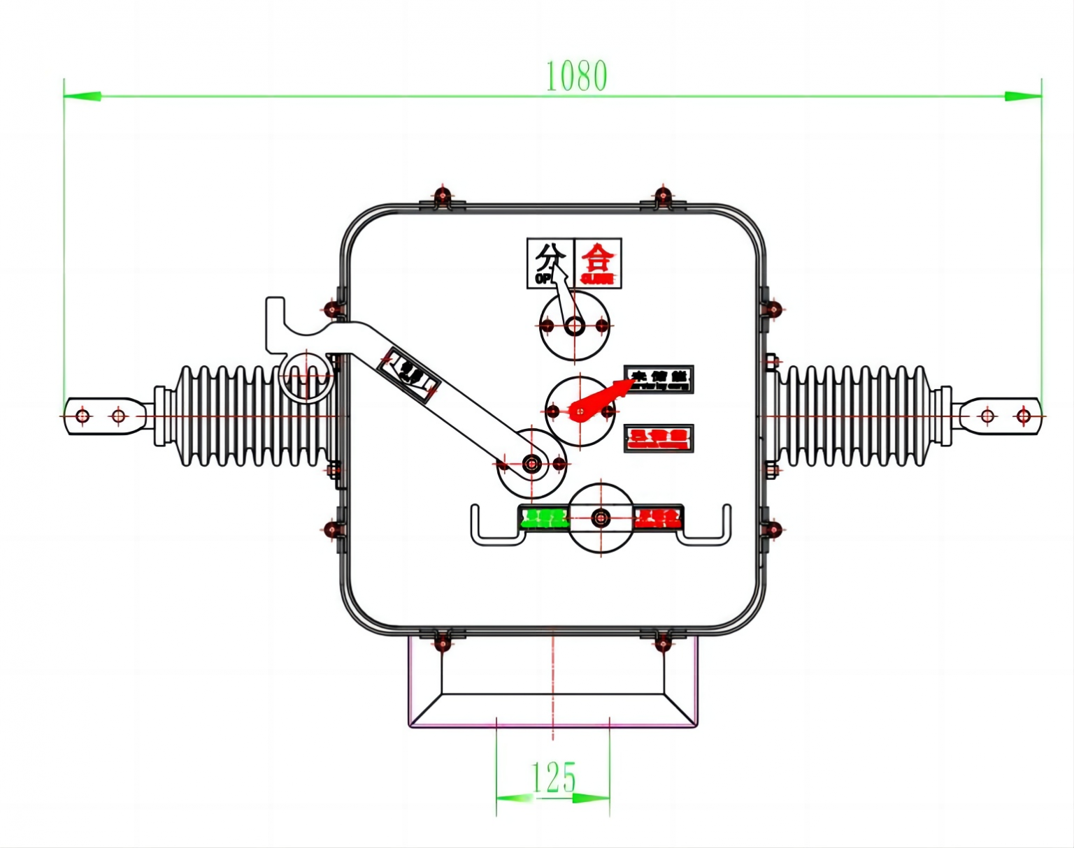
Installation and dimensional references

The drawings show reference arrangements. Their dimensions are not reconciled with the tabulated overall dimensions and must not be combined into one mounting specification. Confirm the applicable drawing and dimension units for the selected equipment before installation.

Pole-mounted equipment installation reference showing earth cable, control cable, switch and control cubicle
Typical pole-mounting arrangement. Open the image to view the original drawing.
Dimensional reference A with source dimensions 1080 and 125
Dimensional reference A — retain the dimensions shown for this illustrated arrangement.
Dimensional reference B with source dimensions 1025, 405, 300, 598, 225, 225 and 500
Dimensional reference B — final interfaces and clearances follow the selected model's approved drawing.

Maintenance

  • Inspect the equipment regularly and remove contamination from insulating surfaces using the specified cleaning method.
  • Check the pressure gauge regularly. Contact the manufacturer if the pointer approaches the red range.
  • For frequently operated equipment, monitor contact wear and keep an operating record. Do not exceed the permitted short-circuit interruption count or mechanical service life.
  • Before maintenance, open the circuit breaker, isolate all power supplies and release stored mechanical energy in accordance with the manual. Stored spring energy can cause unexpected mechanism movement and injury.
  • Maintenance must be performed by qualified personnel. After servicing, particularly after replacing parts or readjustment, verify the mechanical operating characteristics against the applicable technical requirements.

Project-specific customization

The data and illustrations show typical arrangements. Please provide your application, connection and control requirements for configuration review. Feasibility, final ratings, dimensions and the scope of supply will be confirmed for the proposed design.

Discuss your configuration →

Product documents.

Request the applicable documents for your project.

Outdoor Pole-Mounted SF6 Switchgear

Send us a message.

Tell us about your project and the products you need.

+86 18150100999

Factory Building 2, No. 552 Tongji North Road, Tong'an District, Xiamen City, Fujian Province, China 361000
Unit 201, No. 15, Tongfu Beili, Tong'an District, Xiamen City, Fujian Province, China 361000

Request a Quote